Butler System Crankshaft Pulley Installation & Replacement Procedure
It is important before starting this or any other procedure, that you or anyone who operates, works with, maintains, services or repairs the Butler System and/or vehicle, be familiar with its operation and thoroughly read, understand and follow, in their entirety, all of the Warnings, Cautions, and Notices described in your Butler System and vehicle Owners’ Manuals.
Carefully read and understand the complete list of instructions before proceeding.
Purpose: Install, or replace, and adjust, the Butler System Crankshaft Pulley.
Applicable Models: 2003+ Chevrolet, GMC vans and cut-aways, and Isuzu NPR and NQR cab-over trucks with 4.8l, 6.0l, and 6.6l V8 Gas engines.
IMPORTANT: Use only a Butler System Crank Pulley with a YELLOW label. Pulleys identified with a YELLOW label are adjustable and require the following procedure to complete the proper installation. Failure to properly adjust (align) the pulley may result in engine vibration and possible damage to the vehicle and/or Butler System.
Parts to be Installed:
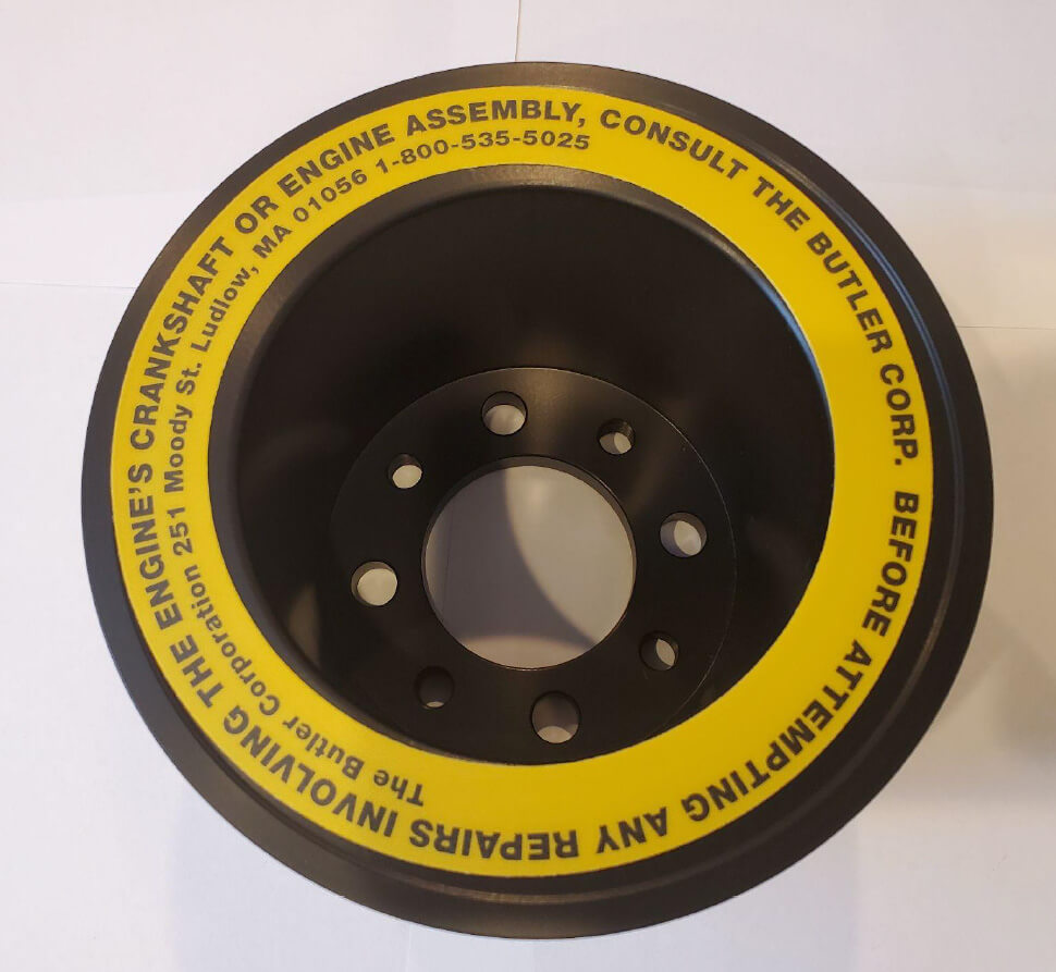
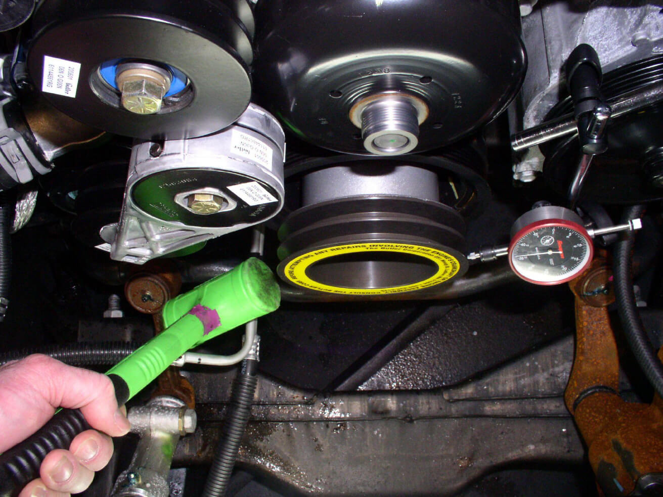
- Butler System Crankshaft Pulley with YELLOW label (shown below)
Special Tools Required:
- Magnetic mount travel dial indicator (shown below)
- ½" drive long handle ratchet
- ½" drive 3" extension
- 1" socket
- 2lb. dead blow mallet
- Torque wrench
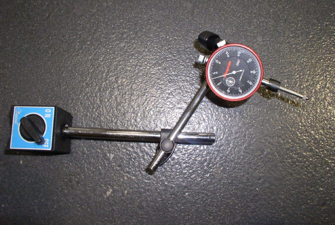
Magnetic mount travel dial indicator can be borrowed from The Butler Corporation upon request.
Removal Procedure:
- Disconnect the negative battery cable.
- Remove the coolant reservoir.
- Remove the air cleaner assembly.
- Remove the upper fan shroud.
- Remove the fan clutch assembly.
- Remove the two Butler System V belts.
- Remove (4) 9/16" bolts from Butler pulley.
- Remove Butler pulley. (may require light tapping with dead blow mallet)
Installation Procedure:
- Install the new Butler System Crankshaft Pulley (with YELLOW label) using four 9/16" bolts with flat and lock washers. Hand tighten only.
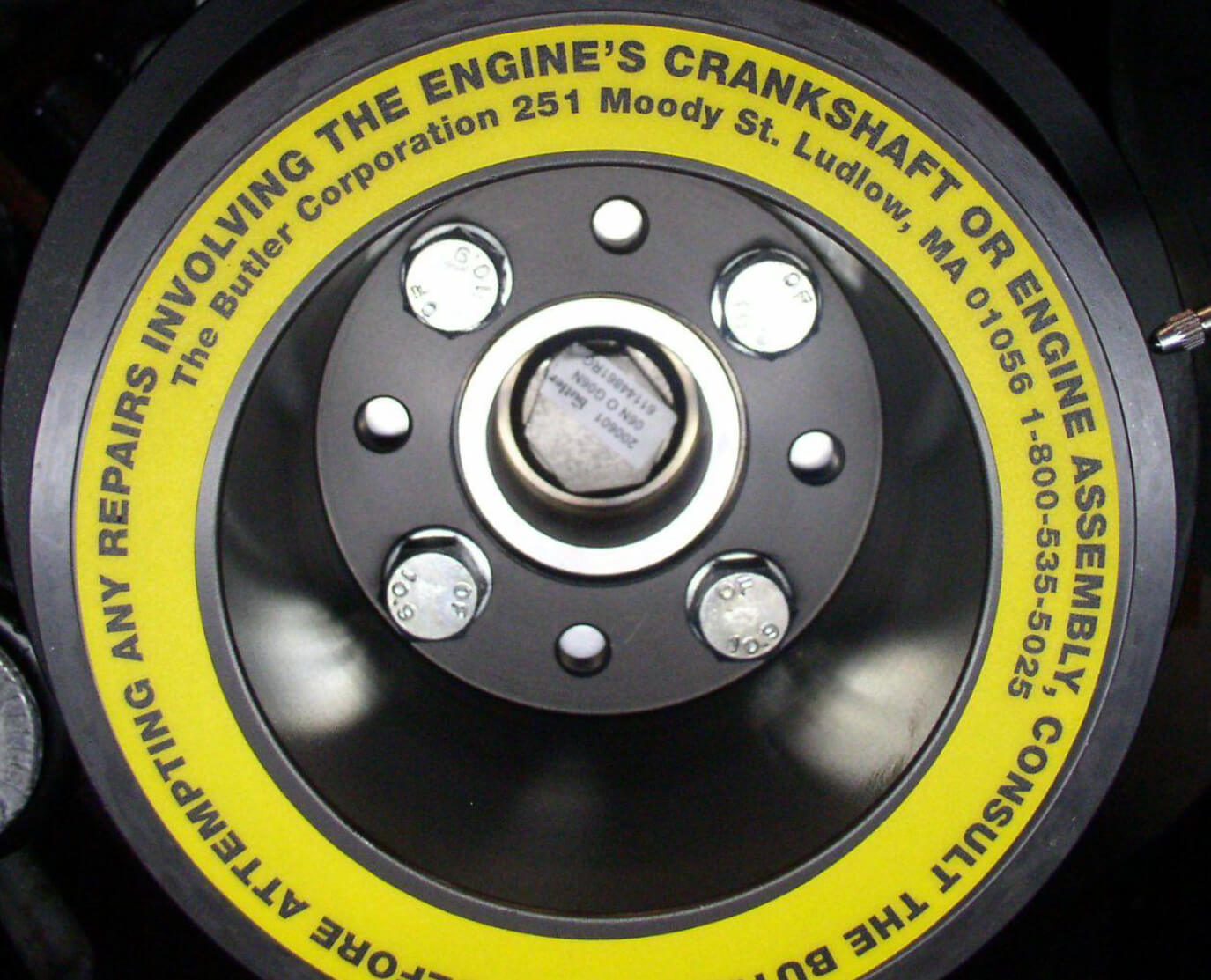
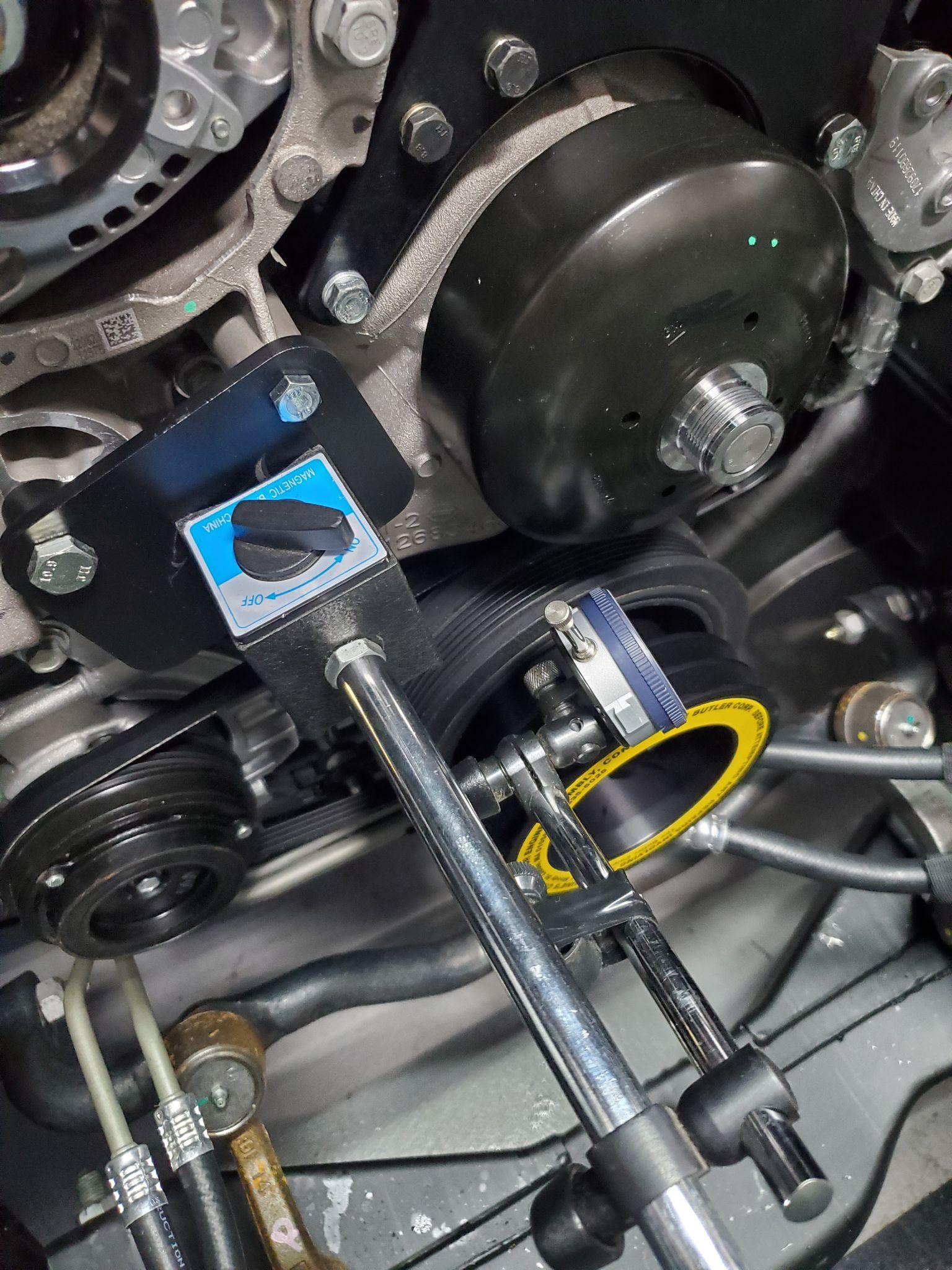
2. Mount magnetic dial indicator to suitable position. (Suggested dial indicator position for 2003-2020 6.0L & 4.8L V8 engines shown below.)
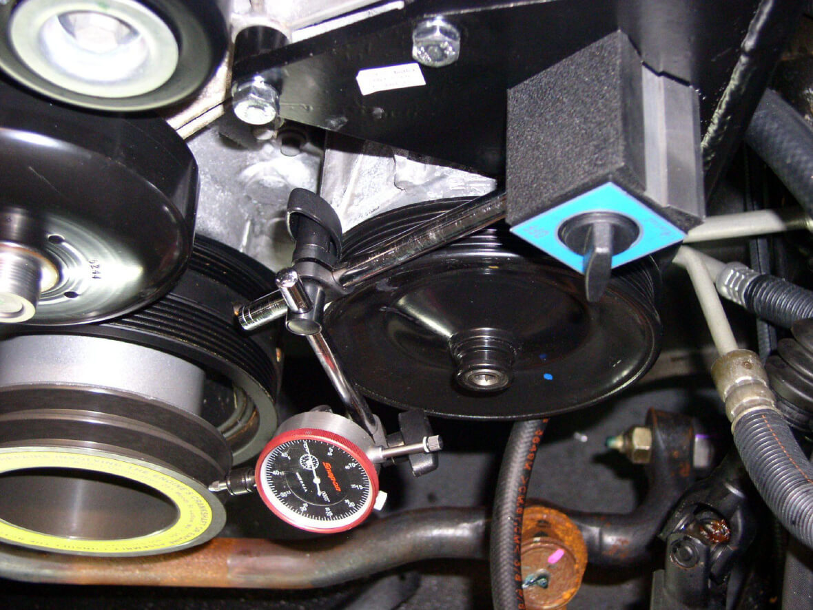
2a. 2021 and newer vehicles with 4.3L V6 & 6.6L V8 engines must use the dial indicator mounting plate available to rent in our crankshaft drill kits and dial indicator kits.(Suggested dial indicator mounting position shown below.)
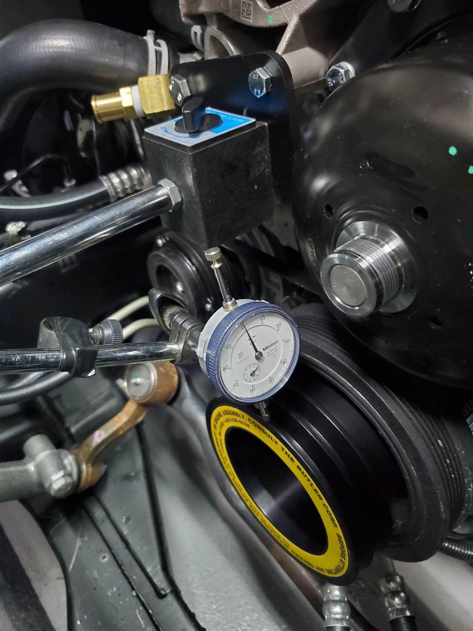
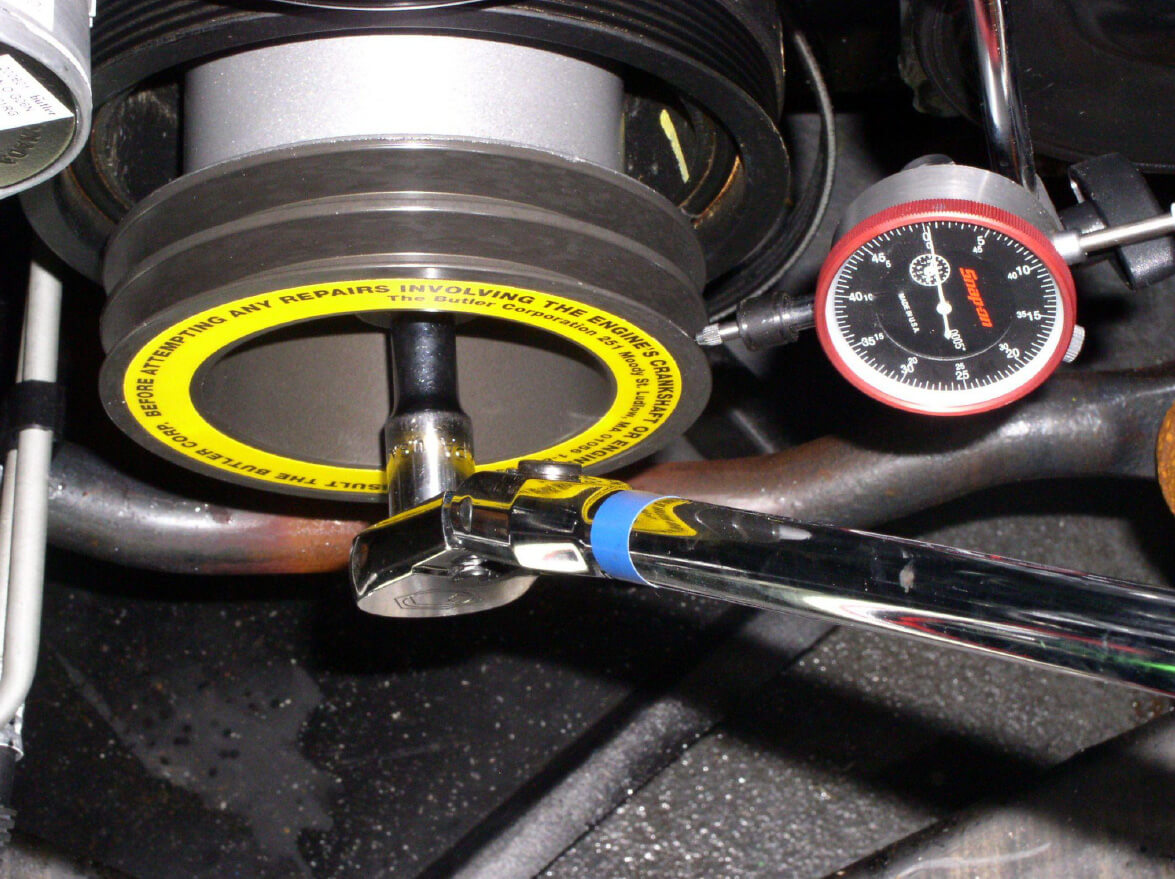
3. Dial indicator reading should be taken at the front ring of the Butler pulley.
4. Using ½" drive ratchet, 3" extension and 1" socket rotate the engine crankshaft clockwise one complete revolution.
5. Note the highest and lowest reading of the dial indicator. Subtract the lowest reading from the highest reading to determine the total dial indicator movement.
6. Continue rotating engine crankshaft clockwise until the lowest point on the pulley is shown on the dial indicator.
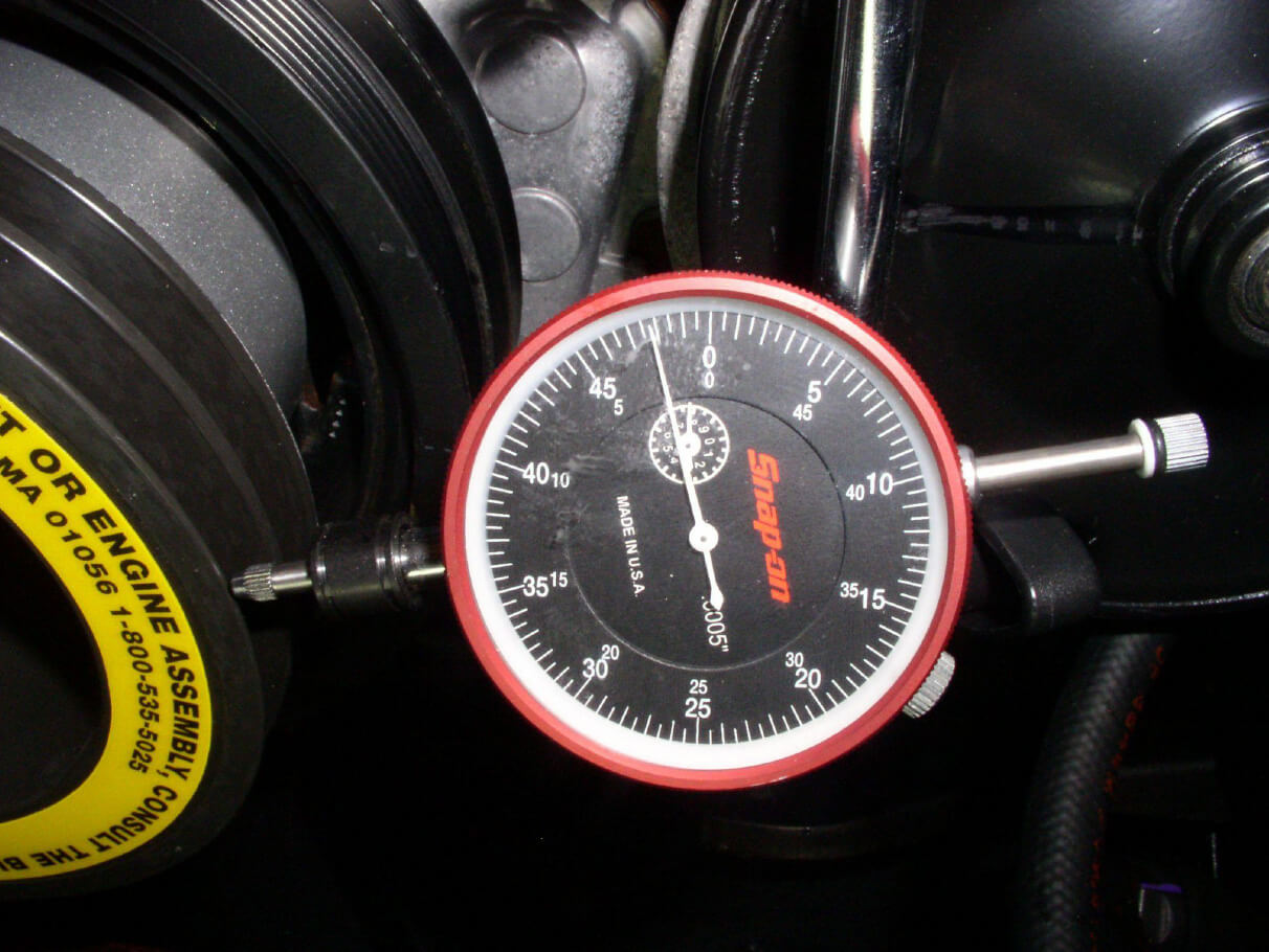
7. Gently tap the pulley towards the dial indicator moving the pulley 50% of total movement noted above (line 5).
8. Example: if total movement noted was .020in you need to tap pulley towards center .010in
9. Rotate engine crankshaft clockwise again noting total dial indicator movement. Total dial indicator movement should be less than .010in, if not repeat steps 3 through 5.
10. Tighten the four pulley bolts to 37lb-ft.
11. Rotate engine crankshaft clockwise again. Total dial indicator movement should remain less than .010.
12. Remove the dial indicator.
13. Install (2) new Butler V belts.
14. Install fan clutch assembly and torque to 70lb-ft.
15. Install upper fan shroud.
16. Install air cleaner.
17. Install coolant reservoir.
18. Connect negative battery cable.
19. Start engine and inspect for any abnormal engine or Butler System Driveshaft vibrations.
If you have any questions, please call the Butler Corporation Service Department at (800)535-5025.
Butler System Crankshaft Pulley Installation & Replacement 20211209